The Prototype
Introduction
In this project, a hybrid
solar vehicle prototype including a thermal engine, an electrical
motor/generator, a battery pack and photovoltaic panels will be developed
and tested. Design, assemblage and testing processes will be presented
on this web site, with particular care of didactic
sides. Design progresses may be followed through the roadmap
and photo
gallery. Within project deadline, the prototype will be tested and
presented to the media and information agencies.
The Choice
In the first stage of the project, different options
have been investigated to build the hybrid solar vehicle prototype. First
of all, it has been considered either to build a new vehicle
all over again or to develop the project starting from an existing
car. Although the first solution appeared to be interesting,
it was not feasible and consistent with time and budget limits. Moreover,
the second option offered a better chance to apply previous know how and
theoretic analyses. At that point, a vehicle typology had to be selected:
a kart or a car, with thermal
or electrical engine. Finally, an existing electric
vehicle was chosen as basic structure for prototype development.
The Structure
A “Series Hybrid Vehicle”
configuration seems to be the most suitable solution to match the framework
chosen. In this case, traction power is supplied only by the electrical
motor (EM/EG), which may operate also as generator during braking mode
(regenerative braking), adopting one of the electric vehicle energy recovery
strategies. Photovoltaic panels (PV) and the motor/generator system (ICE/EG)
either supply power to the electrical motor or charge the battery pack
(Battery), accordingly to control system strategies (Vehicle Management
Unit, VMU). Further details are available in On-line
simulator section.
Series Solar Hybrid Vehicle Typology
The Electric Vehicle
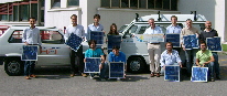
A “Porter Glass Van” by Microvett has been selected
to develop the prototype. It is a light duty vehicle suited for urban
and protected areas, due to the lack of gas emissions and noise. A “Porter
Glass Van” has been provided to the research group by Automobile
Club Salerno (ACS), one of the project sponsors.
Porter
Glass Van donation to research group by ACS
A significant surface for photovoltaic panels housing
is available on the vehicle roof, while motor/generator and control systems
may be placed in the large trunk. The powertrain includes an electric
motor fed by batteries placed under the driver and passenger compartment.
The electric motor may be reached lifting driver seat.
| 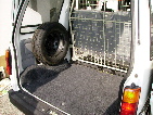
The Rear Bonnet |
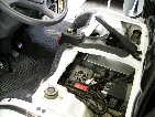
Electric Motor |
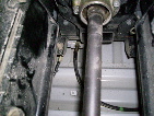
Transmission Shaft |
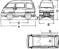
Electric vehicle technical data
Vehicle technical data such as typical sizes, overall volumes,
mass distribution, power provided by batteries and so on are listed in
the following tables.
Sizes |
Meters |
A |
3.560 |
B |
1.395 |
C |
1.870 |
D |
1.810 |
F |
0.540 |
G |
0.793 |
| Engine |
Direct Current Motor |
| Voltage
|
84 V |
| Nominal
power |
9 kW |
| Cooling
flow |
Air |
| Battery pack |
14 6V modules - 180 Ah Pb-Gel sealed, without maintenance |
| Battery charger |
On board - 3 kW - 230 V (standard industrial monophasic
plug) |
| Charging
time |
8 h |
| Rapid
charging |
5 kW - 380 V |
| Rapid
charging time |
2 h 45' @ 80% State of charge |
| Maximum
speed |
60 km/h |
| Range |
70 km in urban duty cicle |
| Transmission |
Direct to the rear axle |
| Steering
radius |
3,7 m |
| Seats |
4 |
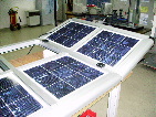
Photovoltaic Panels
Referring to photovoltaic panels, different options have been investigated
and proper choices have been made:
- What kind of panels has to be used? In order to work
on a feasible solution, standard production silicon polycrystalline
panels have been selected, rather than high efficiency gallium arsenide
panels, capable to assure high performance but extremely expensive.
- A single panel or many smaller panels? The second
option has been followed to optimize single panel control as a function
of temperature and incoming solar radiation conditions, that may vary
on different panels.
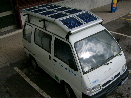
- How may panels be mounted on the vehicle? May they
be integrated in the roof or an external support has to be provided?
First solution guarantees a better aerodynamics and an enjoyable look.
Second option assures higher flexibility during design stage and suggests
innovative ideas. For example, when vehicle is parked, panel orientation
may change following sun position. Finally, a travelling platform has
been chosen, taking into account that aerodynamic losses are negligible
due to vehicle low speed. Following the roof profile by means of two
articulations, an aluminium platform has been built by Saggese company
and donated to the research group.
| 
|
|
|
| |
The support for solar panels |
The solar panels are on the roof! |
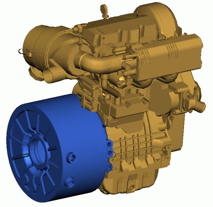
The motor/generator system
Firstly, we have tried to use a motor-generator system
offered by Lombardini: a 15 KW two-cylinder gasoline engine water cooled.
A solution characterized by a favourable power to weigth ratio, by limited
sizing and power level adequate to vehicle demand.
|
|
Scheme of the Lombardini motor-generator system |
Torque, power and specific consumption of
Lombardini group |
The technical data are summarized in the following table:
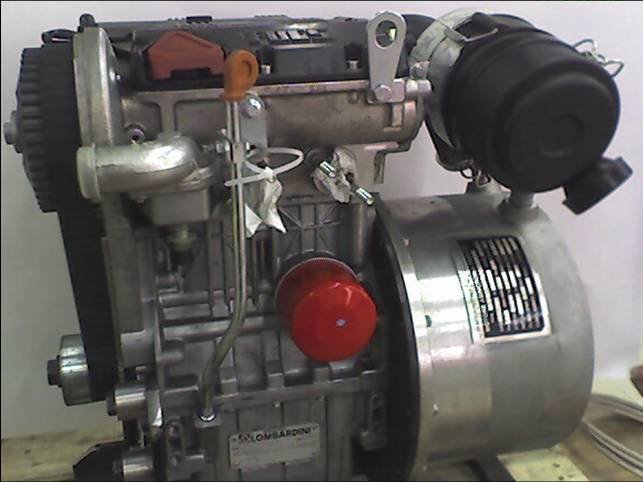
Lombardini 500cc LGW523 ENGINE
Max power 15 [kW] @ 5000 [rpm]
3 phase induction MACHINE 15 [kW] power rated
0 - 6000 [rpm] speed range
200 - 400 [V] DC voltage range
100 [A] DC max current
|
Lombardini Motor-Generator - Technical Data |
In order to remove the heat generated by the the cooling
system, the original radiator
used on the vehicle has been recovered and mounted, at CIMEP laboratories.
Moreover, intake
air inlet and exhaust
gas discharge outlet have been realized.
|
|
|
The Lombardini group |
The generator is mounted on board |
Working at CIMEP Labs |
This choice has posed some additional problems:
- the output voltage was higher than the one needed to charge the batteries;
- electric generator power was higher and not compatible with the circuits
already mounted on board;
- the electric machine needs a complex control system to work as motor
during start-up and to shift to generator mode after thermal engine
start.
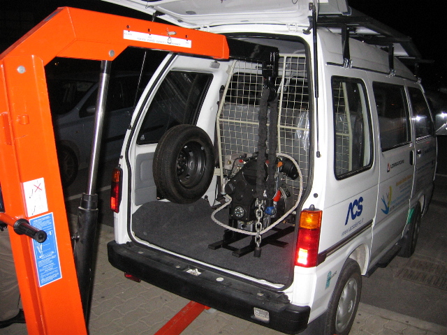
A second motor-generator group
The solution of these problems did not appear compatible with the time
scheduling of the project. Therefore, a second solution has been chosen:
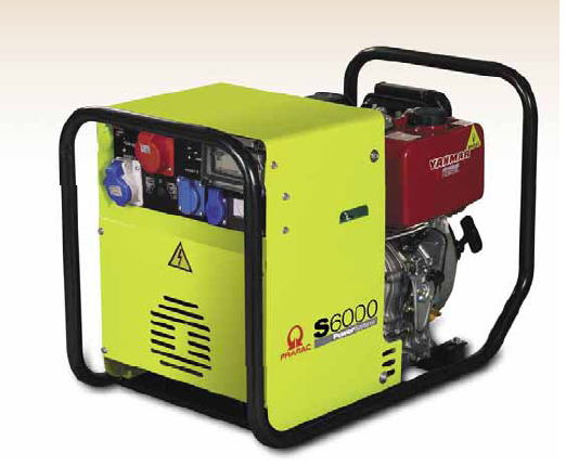
a 6 KW YANMAR S6000 single-cylinder Diesel engine, air cooled, with electric
starter. This generator, although less powerful respect to Lombardini,
allowed to overcome the problems cited in 1,2,3. In particular, the electric
output, at 230 V, was directly linkable to the vehicle circuitry. Technical
data of YANMAR group are available at this
link.
|
|
The YANMAR motor-generator system |
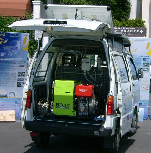
The YANMAR motor-generator system on the back
side of the vehicle |
The YANMAR has been soon renamed "o' per e o' muss",
thanks to its similarity with the groups used by the street vendors of
the famous neapolitan speciality.
The group has been mounted on the back trunk, using the mechanical supports
and the apparatus already available on board. It has been necessary to
disable a security block that was preventing battery recharging when the
vehicle was moving. Therefore, the engine start has been automated and
suitable potentiometers
have been mounted on gas and brake pedals.
Noise
Of course, mounting a motor-generator into the passenger compartment
is not precisely the best solution in terms of comfort (and safety). Therefore,
an acoustic insulator has been designed and realized,
with the support of Saggese. A window, with double glass layer, has been
inserted to assure back visibility to the driver. A sandwich of insulating
material has been chosen, with lead thin layer and a sponge rubber, to
cut low and hgigh frequencies. In this way, a satisfying noise
reduction has been obtained.
Work in progress...

We are now working to connect an electro-mechanical actuator to regulate
engine load and to mount the equipment for data
acquisition and vehicle control.
…to be continued
|


