 |
 |
 
|
 |
Partners


|
 
This project has been
funded with support from the European Commission
Red Links: Search on Wikipedia
C.Mascolini, Daliento, C.Del Plato (*) - I.Ionita (**) (*) Istituto Alfano I - (**) University of Galati ThermodynamicsSummaryThermodynamics is the science of the relationship between heat, work, and systems that analyze energy processes. The energy processes that convert heat energy from available sources such as chemical fuels into mechanical work are the major concern of this science. Thermodynamics consists of a number of analytical and theoretical methods which may be applied to machines for energy conversion.First Law of ThermodynamicsThe first law of thermodynamics is the application of the conservation of energy principle to heat and thermodynamic processes:
The first law makes use of the key concepts of internal energy, heat, and system work. It is used extensively in the discussion of heat engines. It is typical for chemistry texts to write the first law as ΔU=Q+W. It is the same law, of course - the thermodynamic expression of the conservation of energy principle. It is just that W is defined as the work done on the system instead of work done by the system. In the context of physics, the common scenario is one of adding heat to a volume of gas and using the expansion of that gas to do work, as in the pushing down of a piston in an internal combustion engine. In the context of chemical reactions and process, it may be more common to deal with situations where work is done on the system rather than by it. EnthalpyFour quantities called "thermodynamic potentials" are useful in the chemical thermodynamics of reactions and non-cyclic processes. They are internal energy, the enthalpy, the Helmholtz free energy and the Gibbs free energy. Enthalpy is defined by H = U + PV where P and V are the pressure and volume, and U is internal energy. Enthalpy is then a precisely measurable state variable, since it is defined in terms of three other precisely definable state variables. It is somewhat parallel to the first law of thermodynamics for a constant pressure system Q = ΔU + PΔV since in this case Q=ΔH
The internal energy U might be thought of as the energy required to create a system in the absence of changes in temperature or volume. But if the process changes the volume, as in a chemical reaction which produces a gaseous product, then work must be done to produce the change in volume. For a constant pressure process the work you must do to produce a volume change ΔV is PΔV. Then the term PV can be interpreted as the work you must do to "create room" for the system if you presume it started at zero volume. System WorkWhen work is done by a thermodynamic system, it is usually a gas that is doing the work. The work done by a gas at constant pressure is: The line from a to b represents an expansion of a gas at constant pressure. The work done is the area under the curve. For non-constant pressure, the work can be visualized as the area under the pressure-volume curve which represents the process taking place. The more general expression for work done is: The integral gives the exact area under the curve which is equal to the work. Work done by a system decreases the internal energy of the system, as indicated in the First Law of Thermodynamics. System work is a major focus in the discussion of heat engines. Second Law of ThermodynamicsThe second law of thermodynamics is a general principle which places constraints upon the direction of heat transfer and the attainable efficiencies of heat engines. In so doing, it goes beyond the limitations imposed by the first law of thermodynamics.The maximum efficiency which can be achieved is the Carnot efficiency. Second Law: Heat EnginesSecond Law of Thermodynamics: It is impossible to extract an amount of heat QH from a hot reservoir and use it all to do work W. Some amount of heat QC must be exhausted to a cold reservoir. This precludes a perfect heat engine. This is sometimes called the "first form" of the second law, and is referred to as the Kelvin-Planck statement of the second law. Second Law: EntropySecond Law of Thermodynamics: In any cyclic process the entropy will either increase or remain the same: Entropy: a state variable whose change is defined for a reversible process at T where Q is the heat absorbed. Entropy: a measure of the amount of energy which is unavailable to do work. Entropy: a measure of the disorder of a system. Entropy: a measure of the multiplicity of a system. Since entropy gives information about the evolution of an isolated system with time, it is said to give us the direction of "time's arrow" . If snapshots of a system at two different times shows one state which is more disordered, then it could be implied that this state came later in time. For an isolated system, the natural course of events takes the system to a more disordered (higher entropy) state. Heat Engine ProcessesHeat engine processes are shown on a PV diagram. Besides constant pressure, volume and temperature processes, a useful process is the adiabatic process where no heat enters or leaves the system.
The Diesel EngineThe diesel internal combustion engine differs from the gasoline powered Otto cycle by using a higher compression of the fuel to ignite the fuel rather than using a spark plug ("compression ignition" rather than "spark ignition"). 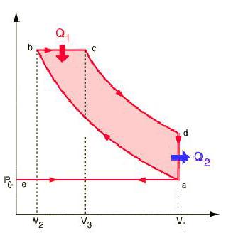
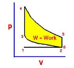
In the diesel engine, air is compressed adiabatically with a compression ratio typically between 15 and 20. This compression raises the temperature to the ignition temperature of the fuel mixture which is formed by injecting fuel once the air is compressed. The ideal air-standard cycle is modeled as a reversible adiabatic compression followed by a constant pressure combustion process, then an adiabatic expansion as a power stroke and an iso-volumetric exhaust. A new air charge is taken in at the end of the exhaust, as indicated by the processes a-e-a on the diagram. Since the compression and power strokes of this idealized cycle are adiabatic, the efficiency can be calculated from the constant pressure and constant volume processes. The input and output energies and the efficiency can be calculated from the temperatures and specific heats: It is convenient to express this efficiency in terms of the compression ratio rC = V1/V2 and the expansion ratio rE = V1/V3. The efficiency can be written Now using the ideal gas law PV= n R T and g= CP/CV, this can be written Now using the fact that Va = Vd = V1 and Pc=Pb from the diagram Dividing the numerator and denominator by V1Pc Now making use of the adiabatic condition PVg= constant, the efficiency can be written The Otto Enginecv Specific Heat constant volume γ Specific Heat Ratio p pressure T temperature V volume f fuel/air ratio Q Fuel heating value Cps cycles per secomd P power Compression stroke: Combustion: Power Stroke: Work per cycle: Engine Power: Ideal Otto Cycle On the figure we show a plot of pressure versus gas volume throughout one cycle. We have broken the cycle into six numbered stages based on the mechanical operation of the engine. For the ideal four stroke engine, the intake stroke (1-2) and exhaust stroke (6-1) are done at constant pressure and do not contribute to the generation of power by the engine. During the compression stroke (2-3), work is done on the gas by the piston. If we assume that no heat enters the gas during the compression, we know the relations between the change in volume and the change in pressure and temperature from our solutions of the entropy equation for a gas. We call the ratio of the volume at the beginning of compression to the volume at the end of compression the compression ratio, r. Then where p is the pressure, T is the temperature, and γ is the ratio of specific heats. During the combustion process (3-4), the volume is held constant and heat is released. The change in temperature is given by where Q is the heat released per pound of fuel which depends on the fuel, f is the fuel/air ratio for combustion which depends on several factors associated with the design and temperature in the combustion chamber, and cv is the specific heat at constant volume. From the equation of state, we know that: During the power stroke (4-5), work is done by the gas on the piston. The expansion ratio is the reciprocal of the compression ratio and we can use the same relations used during the compression stroke: Between stage 5 and stage 6, residual heat is transferred to the surroundings so that the temperature and pressure return to the initial conditions of stage 1 (or 2). During the cycle, work is done on the gas by the piston between stages 2 and 3. Work is done by the gas on the piston between stages 4 and 5. The difference between the work done by the gas and the work done on the gas is shown in yellow and is the work produced by the cycle. We can calculate the work by determining the area enclosed by the cycle on the p-V diagram. But since the processes 2-3 and 4-5 are curves, this is a difficult calculation. We can also evaluate the work W by the difference of the heat into the gas minus the heat rejected by the gas. Knowing the temperatures, this is an easier calculation. The work times the rate of the cycle (cycles per second cps) is equal to the power P produced by the engine. The efficiency is: Links
http://hyperphysics.phy-astr.gsu.edu/hbase/heacon.html#heacon
|
|||||||||||||||||


 |
|
|
 |


